Coordinate Transformation Problem
Brief description of the problem
When performing transformation calculations using vector-quaternion composition, if the parent node applies a rotation, the non-uniform scaling of its child nodes may result in unexpected changes to the scaling effect due to changes in the coordinate system.
For non-uniform scaling, Unity 2022 and UE 5.4 handle it as follows.
UE5.4 uses a combination of vector quaternions for calculations. This results in the following phenomenon: when the parent node Actor2 applies non-uniform scaling (e.g., scaling only along its local X-axis), the child node Actor4 is affected by the rotation of its parent node Actor3 (e.g., a 90-degree rotation around the Y-axis). As a result, the scaling changes of the child node in the parent node Actor2's coordinate system are no longer along the expected X-axis but along the Z-axis. This will result in the following issues.
Unity handles this as follows: under the cube node, scale the x-axis. Regardless of how the cube1 node rotates, its child node cube2 will only change its x-axis displacement in the cube parent node coordinate system.
Reason
This issue is caused by the combination of vector/quaternion transformations based on the parent node's coordinate system in UE5.4. Specifically, after a Scale transformation, the coordinate system used to calculate the world position remains based on the parent node's original space. As a result, this calculation is influenced by the parent node's rotation. Additionally, non-uniform scaling inherently has directionality, meaning the magnitude of changes varies across different coordinate axes.
The following code shows the FTransform multiplication operation in UE5.4:
x// Node Transform update:FTransform USceneComponent::CalcNewComponentToWorld_GeneralCase(const FTransform& NewRelativeTransform, const USceneComponent* Parent, FName SocketName) const{ if (Parent != nullptr) { const FTransform ParentToWorld = Parent->GetSocketTransform(SocketName); FTransform NewCompToWorld = NewRelativeTransform * ParentToWorld; if(IsUsingAbsoluteLocation()) { NewCompToWorld.CopyTranslation(NewRelativeTransform); }
if(IsUsingAbsoluteRotation()) { NewCompToWorld.CopyRotation(NewRelativeTransform); }
if(IsUsingAbsoluteScale()) { NewCompToWorld.CopyScale3D(NewRelativeTransform); }
return NewCompToWorld; } else { return NewRelativeTransform; }}
/** Returns Multiplied Transform of 2 FTransforms **/template<typename T>FORCEINLINE void TTransform<T>::Multiply(TTransform<T>* OutTransform, const TTransform<T>* A, const TTransform<T>* B){ A->DiagnosticCheckNaN_All(); B->DiagnosticCheckNaN_All();
checkSlow(A->IsRotationNormalized()); checkSlow(B->IsRotationNormalized());
// When Q = quaternion, S = single scalar scale, and T = translation // QST(A) = Q(A), S(A), T(A), and QST(B) = Q(B), S(B), T(B)
// QST (AxB)
// QST(A) = Q(A)*S(A)*P*-Q(A) + T(A) // QST(AxB) = Q(B)*S(B)*QST(A)*-Q(B) + T(B) // QST(AxB) = Q(B)*S(B)*[Q(A)*S(A)*P*-Q(A) + T(A)]*-Q(B) + T(B) // QST(AxB) = Q(B)*S(B)*Q(A)*S(A)*P*-Q(A)*-Q(B) + Q(B)*S(B)*T(A)*-Q(B) + T(B) // QST(AxB) = [Q(B)*Q(A)]*[S(B)*S(A)]*P*-[Q(B)*Q(A)] + Q(B)*S(B)*T(A)*-Q(B) + T(B)
// Q(AxB) = Q(B)*Q(A) // S(AxB) = S(A)*S(B) // T(AxB) = Q(B)*S(B)*T(A)*-Q(B) + T(B) checkSlow(VectorGetComponent(A->Scale3D, 3) == 0.f); checkSlow(VectorGetComponent(B->Scale3D, 3) == 0.f);
if (Private_AnyHasNegativeScale(A->Scale3D, B->Scale3D)) { // @note, if you have 0 scale with negative, you're going to lose rotation as it can't convert back to quat MultiplyUsingMatrixWithScale(OutTransform, A, B); } else { const TransformVectorRegister QuatA = A->Rotation; const TransformVectorRegister QuatB = B->Rotation; const TransformVectorRegister TranslateA = A->Translation; const TransformVectorRegister TranslateB = B->Translation; const TransformVectorRegister ScaleA = A->Scale3D; const TransformVectorRegister ScaleB = B->Scale3D;
// RotationResult = B.Rotation * A.Rotation OutTransform->Rotation = VectorQuaternionMultiply2(QuatB, QuatA);
// TranslateResult = B.Rotate(B.Scale * A.Translation) + B.Translate const TransformVectorRegister ScaledTransA = VectorMultiply(TranslateA, ScaleB); const TransformVectorRegister RotatedTranslate = VectorQuaternionRotateVector(QuatB, ScaledTransA); OutTransform->Translation = VectorAdd(RotatedTranslate, TranslateB);
// ScaleResult = Scale.B * Scale.A OutTransform->Scale3D = VectorMultiply(ScaleA, ScaleB); }}
The global position of the parent node and the local position of the current node under the parent node The code for calculating the position of the current node in World Space can be written as:
mDerivedPosition = parentOrientation * (DBVector3(parentScale) * mPosition) + parentPosition
When scaling uniformly, mPosition is affected by the parent node Scale in the same way in each direction, so regardless of how rotation changes occur, the unit increments of X, Y, and Z are the same.
When non-uniform scaling is applied, such as scale=(2,1,1), the Step along the x-axis becomes 2 after applying the Scale transformation. Then, a rotation of -90 degrees around the y-axis is applied. At this point, the x-axis moves to the position of the z-axis, and the z-axis moves to the position of the -x-axis. Therefore, in the global coordinate system, the coordinate axis with an increment of 2 for the current node changes from the x-axis to the z-axis.
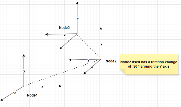
With Node1 as the global coordinate system, when scale=(2,1,1) is applied to the parent node Node1, the displacement of the x-axis is stretched by 2 times.
Then Node2 undergoes a transformation: Node2 position = Node1 position + Node1 rotation × (Node1 scale × Node2 local position).
At this point, Node2 still undergoes non-uniform scaling along the X-axis in the global coordinate system.
When Node3 changes, first scale the X-axis, then rotate the X-axis to the Z-axis position. Therefore, in the global coordinate system, the original X-axis scale change becomes a Z-axis scale change. When scale = (2,1,1), due to the rotation effect, nodes above Node2 in the global coordinate system change along the X-axis, but nodes below Node2 in the global coordinate system actually change along the Z-axis.
(First rotate 90 degrees around the Y-axis, then scale 2 times along the X-axis) Changes from [1,1,1] to [1,1,-2]. In the global coordinate system, the actual change is in the Z-axis value.
As shown in the figure below, calculations are performed using a combination of vectors and quaternions.
Root Node: Its local coordinate system is a unit orthogonal coordinate system, and no transformations have been applied.
Node 1: Relative to its parent node (i.e., the root node), a translation transformation (1, 1, 1) and a rotation transformation (rotation of 90 degrees around its local Y-axis) have been applied.
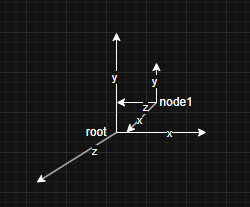
There is a point q in node1, with a localPosition of (1,1,1) under node1 and a DerivedPosition of (2,2,0) under the root node.
If root is attached to a scene node, and the scene has a scale of (2,1,1), a scale change of scale=(2,1,1) is applied to the root coordinate system. At this point, the changes to root and node1 are:
The change in point q At this point, DerivedPosition under the scene node is (3,2,-1)
Then, convert point q to the local coordinate system of the root node, where its coordinates are (3/2, 2, -1). This is inconsistent with the original coordinates of point q under the root node (2, 2, 0) before the non-uniform scaling change.
The method of combining vector/quaternion transformations based on the parent node's coordinate system causes the scaling of a node to depend on the rotation direction of its parent node, resulting in inconsistencies with the expected position after scaling along the X-axis in the global coordinate system.
In this example, the expectation is that all X-axis data in the root coordinate system should change. However, when this scaling is applied to point q, point q is affected by the rotation of its parent node node1. In the global coordinate system, the actual scaling change occurs along the Z-axis, while the X-axis data remains unchanged because it was not scaled. As a result, when converting back to the root coordinate system, the scaling factor must still be applied, causing the X-coordinate data to decrease.
As shown in the following video, when using vector quaternions to calculate the global coordinate system and performing non-uniform scaling on nodes at the origin, the scaling axis in the global coordinate system for the third node is no longer the X-axis due to the rotation of the second node (white text indicates the global coordinates, the red line is the X-axis, the blue line is the Z-axis, and the green line is the Y-axis).
Solutions
I tried three solutions:
Use matrix world transformation, then decompose the matrix.
xxxxxxxxxxglm::mat4 Node::getLocalTransform() const {    glm::mat4 translation = glm::translate(glm::mat4(1.0f), mLocalPosition);    glm::mat4 rotation = glm::toMat4(mLocalOrientation);    glm::mat4 scale = glm::scale(glm::mat4(1.0f), mLocalScale);
    return translation * rotation * scale;}
void Node::updateTransforms(const glm::mat4& parentWorldMatrix) {    const glm::mat4 worldTransform = parentWorldMatrix * getLocalTransform();
    mDerivedPosition = glm::vec3(worldTransform[3]);    mDerivedScale = glm::vec3    (        glm::length(glm::vec3(worldTransform[0])),        glm::length(glm::vec3(worldTransform[1])),        glm::length(glm::vec3(worldTransform[2]))    );    mDerivedOrientation = glm::quat_cast(worldTransform);
    for (auto& child : mChildren)     {        child->updateTransforms(worldTransform);    }}
Use this method to scale the root node non-uniformly:
However, the issue with this method is that, due to the mixed calculation of scaling and rotation matrices, the DerivedScale and DerivedOrientation extracted from the final WorldTransform matrix are inconsistent with the original DerivedScale and DerivedOrientation that constituted the WorldTransform.
Rotate first, then scale (not sure about feasibility). When the node applying scaling has a rotation change, the expected scaling change axis should also change. For example, if scale = (2, 1, 1) and there is a 90-degree clockwise rotation around the Y-axis, based on matrix multiplication Translate * Rotation * Scale, the expected scaling change axis for this node should be the Z-axis, but using this method, the axis that always changes is the X-axis.
xxxxxxxxxx mDerivedPosition = DBVector3(parentScale) * (parentOrientation * mPosition) + parentPos;Uniform shrinkage produces the same effect as the original method, and at this point, the multiplication of RS is commutative.
convert the transform of all nodes to the actual changing node space for calculation, which is similar to the method that ue5.4 dragon IK plug-in needs to take the transform of all bones of the character in model space when calculating IK.
xxxxxxxxxxglm::vec3 Node::converPositionLocalToWorld(glm::vec3& position){    return mDerivedPosition + (mDerivedOrientation * (mDerivedScale * position));}
void transformNodeToWorld(std::shared_ptr<Node> node, std::shared_ptr<Node> transform){    if (node == nullptr) { return; }    glm::vec3 mDerivedPosition = node->getDerivedPosition();    glm::quat mDerivedOrientation = node->getDerivedOrientation();    glm::vec3 mDerivedScale = node->getDerivedScale();
    node->setDerivedPosition(transform->converPositionLocalToWorld(mDerivedPosition));    node->setDerivedOrientation(transform->converOrientationLocalToWorld(mDerivedOrientation));    node->setDerivedScale(transform->converScaleLocalToWorld(mDerivedScale));
    std::vector<std::shared_ptr<Node>> vec = node->getChildNodes();    for (const auto& item : vec)    {        transformNodeToWorld(item, transform);    }}
The result obtained at this point is consistent with the result of matrix calculation, and there are no issues with matrix restoration scaling and rotation values.
References
Partial code from Unreal 5.4
Contact
e-mail:2574308236@qq.com